Balancing Fault Simulator & PA201-Balancer
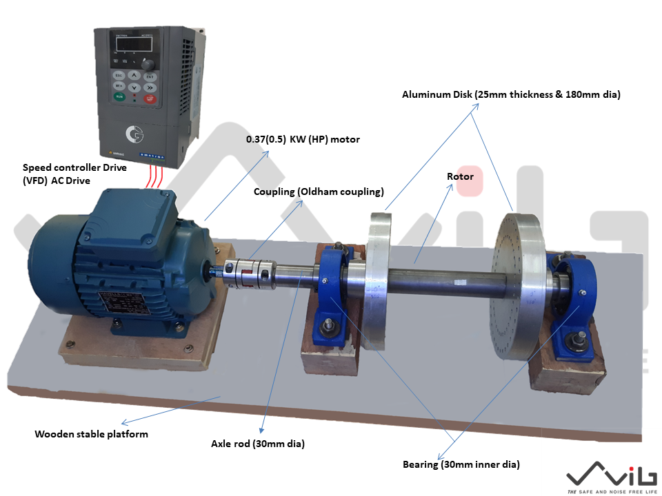
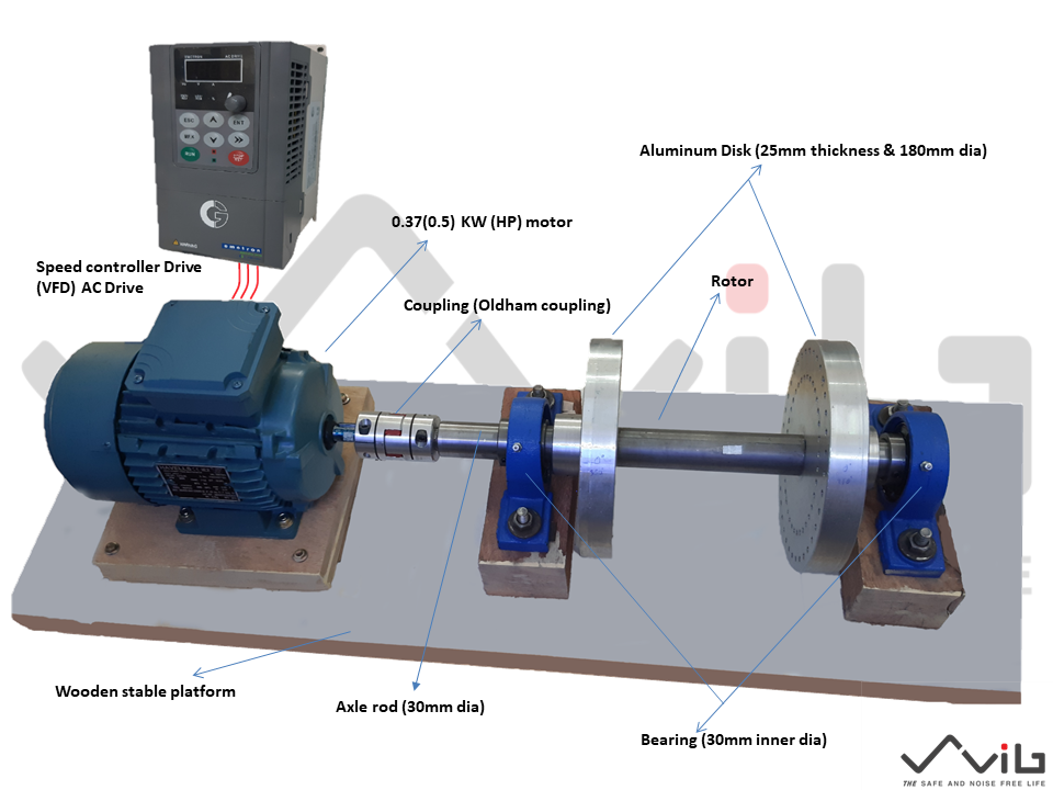
The Balancing Fault Simulator (here onward represent BFS) is specifically designed set up to demonstrate and support the study of unbalance, under controlled conditions. The BFS is a variable speed machine and stable platform that can be used to generate the environment of a single plane or double plane un-balance. Since Balancing related problems are very common, it is essential to have a thorough understanding of the associated fault signatures that occur under a variety of operating conditions. A properly balanced machine will save a factory on machine downtime, replacement parts, inventory, and energy consumption. The BFS provides a basic setup for performing experiments and learning un-balance condition.
Balancing Fault Simulator
An ideal tool to learn multi-plane balancing
&
PA201-Balancer
Smart with handheld device
Table of Contents
- Balancing Fault Simulator (BFS)
- Introduction
- Features
- Causes & Effects of unbalance
- Distortion from stress
- Thermal distortion
- Build-ups and deposits
- Effects
- Causes of an Unbalanced Rotor
- Blow Holes in Castings
- Eccentricity
- Addition of Keys and Keyways (adding of mass)
- Distortion
- Clearance Tolerances
- Corrosion or Wear
- Deposit Build-Up
- Manufactured Unsymmetrical Configurations
- Hydraulic or Aerodynamic Unbalance
- Balancing Limits & ISO Standard
- Types of un-balance
- Static Unbalance
- Couple Unbalance
- Dynamic Unbalance
- Why to use a Balancing Device (Balancer)?
- Solution for un-balanced rotors etc.
- Balancing Device
- Balancing Methods
- Balancing Fault Simulator
- Introduction
The Balancing Fault Simulator (here onward represent BFS) is specifically designed set up to demonstrate and support the study of unbalance, under controlled conditions. The BFS is a variable speed machine and stable platform that can be used to generate the environment of a single plane or double plane un-balance. Since Balancing related problems are very common, it is essential to have a thorough understanding of the associated fault signatures that occur under a variety of operating conditions. A properly balanced machine will save a factory on machine downtime, replacement parts, inventory, and energy consumption. The BFS provides a basic setup for performing experiments and learning un-balance condition.
- Features:
- Portable, robust, cost-effective BFS
- Ideal for teaching one or two-plane balancing within a range of RPM
- User-defined rotation speed (RPM)
- Adding a user-defined mass
Adding the mass at a user-defined angle
Re-run and measure/check balance/un-balance
One plane or two plane balancing possibility
Fig. 1
Balancing Fault Simulator (BFS)
- Causes & Effects of unbalance
2.1 Distortion from stress
- Routine manufacturing processes can cause stress components
- Without stress relief, the rotor will distort itself to adjust
2.2 Thermal distortion
- The thermal
distortion often occurs with parts exposed to increased temperatures
- Metals are able to expand when in contact with heat, so exposure to warmer temperatures can cause either the entire piece of machinery to expand or just certain parts, causing distortion
- Build-ups and deposits
- Rotating parts involved in material handling almost always accumulate build-up
- when exposed to oil, these parts can be very easily distorted
- Without adhering to a maintenance routine or implementing an inspection process, oil can seep into the parts, causing unbalance
- Effects
- More Vibration due to the un-balance
- Loud Noise due to the un-balance
- Decreased life of bearings
- Unsafe work conditions
- Reduced machine life
- Increased maintenance
- Causes of an Unbalanced Rotor
Unbalance is often defined as simply the unequal distribution of the weight of a rotor about its rotating centerline. Causes of unbalance include the following:
3.1 Blow Holes in Castings
- Occasionally, cast rotors such as pump impellers or large sheaves have blow holes or sand traps which result from the casting process
- While undetectable through normal visual inspection, blowholes may be present within the material and create a significant source of unbalance
- Eccentricity exists when the geometric centerline of a part does not coincide with its rotating centerline
- The
rotor itself may be perfectly round; however, for one reason or another, the
center of rotation is off-centered
- Addition of Keys and Keyways (adding of mass)
- A manufacturer may balance their product with a full key, a half key, or no key at all
- Thus, if both a pulley and a motor
manufacturer were to balance their components without keys, they would be
unbalanced when assembled together with the added weight of a key
- Distortion
- Following manufacturer, distortion, or change in shape, can alter the weight distribution and balance of a rotor. Stress-relieving, if not performed during manufacture, is sometimes a problem with rotors which have been fabricated by welding
- Any part that has been shaped by pressing, drawing, bending, extruding, etc., will naturally have high internal stresses
- Over time, they may distort to relieve this stress. Thermal distortion occurs with a change in temperature. Most metals expand when heated. Commonly, rotors will contain minor imperfections and experience uneven heating, causing uneven distortion
- Thermal
distortion is common on machines that operate at elevated temperatures
including electric motors, fans, blowers, compressors, expanders, turbines,
etc. Thermal distortion can sometimes require the rotor to be balanced at its
normal operating temperature.
- Clearance Tolerances
- The most common source of unbalance is the accumulation of tolerances in the assembly process of a machine. An example of when this occurs is when the bore in a pulley is larger than the shaft diameter
- A key or setscrew
would be required to fill the gap, thus pushing the shaft to one side of the
shaft rotating centerline
- Corrosion or Wear
- Many rotors
particularly a fan, blower, compressor, pump rotors, or any other rotors
involved in the material handling processes are subject to corrosion, abrasion,
or wear. If the corrosion or wear does not occur uniformly, then unbalance will
result
- Rotors used in material handling may become unbalanced due to the unequal build-up of deposits (dirt, lime, etc.) on the rotor, the result is a gradual increase in unbalancing can quickly become a serious problem when portions of the deposits begin to break away
- As small deposits
break off, the vibration increases, which in turn, breaks off even more
deposits, thus, creating a serious unbalance
- Many rotors are
manufactured in a way that produces dissymmetry; examples of these include
rough surfaces on forgings, core shifts in castings, uneven number or position
of bolt holes, and unsymmetrical parts, such as crankshafts, etc.
- Hydraulic or Aerodynamic Unbalance
- Oil trapped in oil galleries, oil trapped in grinding wheels and cavitation or turbulence can sometimes produce unbalance forces
In summary, all of the above causes of unbalance can exist to some degree in a rotor. However, the vector summation of all unbalance can be considered as a concentration at a point termed the “heavy spot.” Balancing is the technique for determining the magnitude and location of this heavy spot so that an equal amount of weight can be removed at this location, or an equal amount of weight added directly opposite
- Balancing Limits & ISO Standard
- The International Standard ISO 1940/1 “Balance Quality Requirements of Rigid Rotors” is a widely-accepted reference for selecting rigid rotor balance quality. This standard sets a level of unbalance to be acceptable based on the type of rotor and its operating speed
- While the ISO determines a standardized qualification for balancing, the unbalance tolerance, or the amount of unbalance allowed in a product can easily be determined by the manufacturer
- The best way to determine an acceptable balance tolerance is to experiment with a batch of rotors
- Balance the rotors to reduce unbalance to a minimum. Then slowly add unbalance until the performance becomes unacceptable
- Keep in mind that more unbalance can lead to premature bearing failure or excessive vibration
- Pick a balance tolerance within this range that is cost-effective and achievable with little lost time
- Types of un-balance
- Static Unbalance
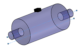
Static unbalance is a condition of unbalance where the central principal axis is displaced parallel to the rotating center line. It can be detected by placing the rotor at its point of rotation on each end. The heavy side of the rotor will swing to the bottom. Apart is considered statically balanced when it does not rotate regardless of the position in which it is placed.
Fig.2
- Couple Unbalance
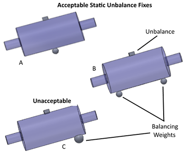
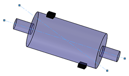
Couple unbalance exists when two unbalances exist 180 degrees apart but in different planes. This condition of unbalance has a central principal mass axis intersecting the rotating centerline. Unlike static unbalance, couple unbalances cannot be detected by allowing the rotor to spin freely. In fact, during the process of static balancing, one can add the weight in the wrong plane, as seen in the Methods of Fixing Static Unbalance. When the weight is added disproportionately, a coupled unbalance is created. Couple unbalances can only be detected when the part is rotating and can be identified by comparing the bearing or shaft vibration amplitude and phase readings at each end of the rotor.
Fig.3
- Dynamic Unbalance
Dynamic unbalance is the most common type of unbalance and is defined simply as unbalance where the central principal axis and the rotating centerline do no coincide or touch. This type of unbalance exists whenever static and couple unbalances are present, but where the static unbalance is not in direct line with either couple component. As a result, the central principal axis is both tilted and displaced from the rotating centerline.
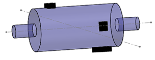
Fig.4
- Why to use a Balancing Device (Balancer)?
- When assessing a rotor, unbalance cannot be visually identified
- A hole or added weight on a rotor may be there from an initial balancing of the rotor, not the cause of unbalance
- The only way to assess unbalance is via the vibration or the force it generates
- In maintenance and overhaul of rotating equipment, there are many cases when it is impractical to attempt in-place balancing because weight corrections cannot be made
- This is true for many pumps and totally enclosed motors as well as turbines and some centrifuges
- Also, the process of repairing a rotor causes gross unbalance which requires balancing prior to reassembling, thereby eliminating possible damage when starting up the machine
- A balancing machine is used to balance parts before re-installation, ensuring the smooth operation of the machine
- A balancing machine can be an extremely valuable asset to any maintenance department that repairs pumps, motors, and other rotating equipment
- It can save costs due to delays by eliminating the need to send parts to outside specialists to be balanced
- Often the savings on one job alone can justify the expense for a balancing machine
- Manufacturers of rotating mechanical equipment must have the assurance that their product will operate smoothly when installing at the final site
- One of the prime concerns is the balancing quality of the rotating components
- Through experience, the manufacturer can establish a tolerable limit of unbalance which can be accepted in a particular machine
- The manufacturer knows that by exceeding this limit, customer complaints and machinery downtime will reflect in the quality of his product
- To meet this situation, parts will be balanced at the time of manufacturer, in most instances, prior to assembly and sometimes trim balanced as an assembly
- Solution for un-balanced rotors etc.
Easy to use, solving the problem, effective result, etc.
7.1 Balancing Device.
Smart Vibration Analyzer with Balancer-PA201

Fig.5
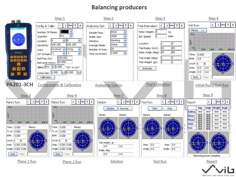
A long time ago, it was essential for a balancing technician to be able to perform all of the balancing calculations, and human error was a potential contributing factor in all balancing situations. Now, everything is automated. When using SV PA201 Balancer machines, one simply follows the instructions on the screen, step by step.
This step is as follows:
1. Chose the Rotor Setup
Our Balancing Instruments are set up to handle the different rotor configurations. Once you choose the rotor configuration, you are instructed to spin the rotor and take a measurement reading, and then stop the rotor.
2. Calibration of the Device with the Rotor
The Balancing Instrument will then instruct the user to add a known weight to the first correcting location on the left hand side, enter the illustrated required dimensions, spin up the rotor and take a measurement, stop the rotor, then remove the left hand weight and place it in the right hand correction plane and repeat. Stop the rotor and remove the known weight. The instrument then uses these measurements to calibrate itself.
3. Balancing the Rotor
The Balancing Instrument now displays both the left- and right-hand correction amounts and the angular location of the correction weights for the addition or subtraction (user-specified) of material.
That’s it! Advancements in technology have turned to balance into a fairly easy task, making it applicable and necessary in every machine shop!
The picture below is a demonstration of the Model PA201 Balancing Instrument. Note, this is the same picture as one of the homepages.
Fig.6
It is imperative that the vibration measurement is a result of the unbalance and not some other exciting force. Only a detailed, thorough, analysis can identify where the vibration measured is coming from. Many sources of vibration can occur at the rotating speed frequency.
When field balancing, trial weights for balance computation and permanent weights for final correction are normally added to the rotor. Care should be taken when attaching weights. They should be attached securely so that they cannot ‘fly off’ when the machine is operating. They not only constitute a personnel safety hazard but also can cause damage. Loose balance weights rattling around inside a turbine, for example, can wreck the machine.
Our field balancing instruments is the Model PA201.

Fig.7


